

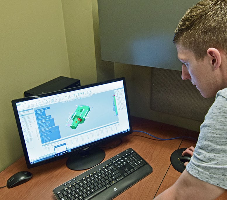
The rise of CAD/CAM software largely defines the current era of manufacturing. While blueprints and dimensional charts are still widely used as reference guides, modern manufacturers rely on software to design prototypes and simulate casting processes. One of the first steps in the cast part development process is to create a 3D model. From there, engineers can improve the part shape, simulate a variety of casting processes and materials, and troubleshoot difficult manufacturing scenarios.
When done right, CAD/CAM software enables foundries to solve all the problems of casting in the virtual world, before pouring any metal. The results are cost savings for the customer, time savings for everyone, and reduction of overall waste.
In this entry to our "Designing Cast Products" blog series, we'll discuss various types of CAD/CAM software and how they fit into the cast product development process.
Designing cast products: creating a 3D model
 Customers provide product designs to foundries in a wide variety of ways. At the Eagle Group, we offer an RFQ form with space to describe the product, upload 2D blueprints or upload pre-existing 3D files. As the preferences and capabilities of each customer varies, foundries need to be ready to handle product design from any stage.
If a customer provides a 2D blueprint illustrating their proposed casting, the foundry can input that dimensional data into 3D modeling software like Solid Edge, SolidWorks or Cimatron. If the customer simply describes the part or provides a list of dimensions, foundry engineers can create 3D models based on that information as well.
Reverse engineering cast parts
If, instead of design specifications or blueprints, the customer provides an existing part, the foundry must reverse engineer the part. Many of these existing parts contain flaws, prompting the customer to seek a new supplier. Even if the parts already function as desired, the best foundries will seek to improve upon the product to offer better appearance, greater durability or cost savings.
Depending on the part shape, the number of critical dimensions and the overall complexity, Eagle Group engineers will obtain dimensional information through hand tools, a handheld laser scanner located at Eagle Alloy, or any of a number of advanced CMMs housed in Eagle CNC's facility.
After obtaining dimensional information, the engineers will input the data into CAD/CAM software to create a 3D model of the part. Just like a model created from scratch, they'll improve design and simulate manufacturing in the virtual world before actually getting started.
In order to further develop the model and optimize it for the real world, foundries then use the APQP process to ask vital questions about the part and how it will be used. The answers to these questions inform every aspect of the simulated part, from material and shape to finishing processes.
Simulating the casting process: solidification simulation software
A major innovation in metal casting in recent years has been the development of solidification simulation software. A specific branch of CAD/CAM software, these applications predict how metal will behave as it enters a mold and cools. Combined with education and experience, foundry engineers can use solidification simulators as tools to choose the optimal casting parameters for each part.
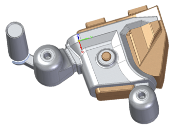
 Solidification simulation software, like MAGMASOFT, shows how metal will enter a mold cavity and behave as it cools. Steel is often poured near 3,000 degrees Fahrenheit, and as it cools in a mold, it shrinks. In order to compensate for shrinkage, foundries include reservoirs of metal, called risers, along the gating. As metal shrinks in the mold, it draws additional material from the risers to fill the mold completely.
While MAGMASOFT is an excellent tool to help foundries predict the outcome of a casting process, it doesn't work without experience and metallurgical knowledge. The software can only take into account the parameters entered by the operator. It's up to an imaginative and experienced operator to determine the best combination to result in the best quality product.
Some parameters that can be adjusted in solidification software (and in the real world) include:
- Pouring temperature
- Pouring speed
- Alloy poured
- Outside temperature
- Core & mold material
- Core & mold thickness
- Riser location
- Chill location
According to Eagle Alloy CTO Nic Tarzwell:
"We see 95-98% correlation between our MAGMA results and real life, but it didn't start off like that. We spent a couple years and hundreds of iterations running side-by-side trials to gather information between virtual and real world results. With this detailed information we were able to customize MAGMA to match our exact foundry parameters–from molding to solidification–to produce our high confidence of success."
"The bottom line is this process still continues today as we seek to further improve our success rates with all alloys and casting shapes as they continue to evolve with this growing industry towards more advanced designs."
CAD/CAM software for inspection
 After completing product design and solidification simulation, the foundry is ready to produce a sample run of parts. They'll use these samples to measure consistency, and ensure that the processes and design they've selected result in defect-free parts conforming to the desired tolerance range.
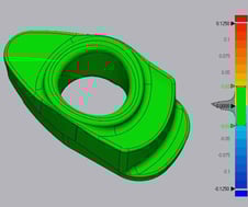
Modern foundries, like Eagle Alloy, take advantage of laser scanners during the inspection process. Instead of painstakingly measuring dozens of points on every sample part with hand tools, they'll scan the parts with a handheld laser scanner. The resulting data can be visualized as a mesh, representing a very close digital representation of the actual part. These meshes can then be overlaid on a 3D model representing the part's nominal dimensions, and the operators can see exactly where the part conforms to tolerance and where it doesn't.
Not only a great tool for foundries, dimensional overlays make it much easier for the customer to confirm that the product will meet their expectations and perform as expected.
To learn more about the design process for cast products, take a look at these other blogs in our "Designing Cast Products" series:
- APQP: Asking the Right Questions
- How to Start Casting with the Eagle Group
- High-Tech Casting Inspection: Eagle Alloy's Handheld Laser Scanner
Curious what a world class metal manufacturing group is capable of achieving? Download the Eagle Group's Quick Reference Guide, including specifications, tolerances and design recommendations for all of our casting and machining services.

Tags: Product Design, Development, Capabilities, Inspection, Product Development, Technology, CAD/CAM

Written by Deb Pipoly
Deb Pipoly is President of Eagle Precision Cast Parts, an investment casting company located in Muskegon, MI.