

Product development processes vary widely from foundry to foundry. The Eagle Group's Product Development blog series aims to highlight practices used by leading foundries that prioritize quality in every part they produce.
One product development practice that sets Eagle Alloy apart from other shell molding foundries is their use of a handheld laser scanner for inspection and dimensional reporting. This technology greatly improves the accuracy of dimensional reports, and makes it easier for customers to verify that new parts meet their requirements.
The importance of inspection for foundries
Inspection plays a huge role in product development. After engineers draft product designs, order tools and produce a sample run of new parts, they must demonstrate that those parts conform to specified tolerance ranges. However, the foundry's ability to verify parts is often limited by their inspection capabilities. Hand tools, and even CMMs, present obstacles that make obtaining accurate measurements difficult and time consuming. By utilizing the laser scanner, Eagle Alloy is able to provide easy-to-read, accurate tolerance reports and clearly pinpoint any areas that need improvement.

How the handheld laser scanner works
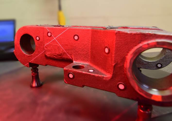
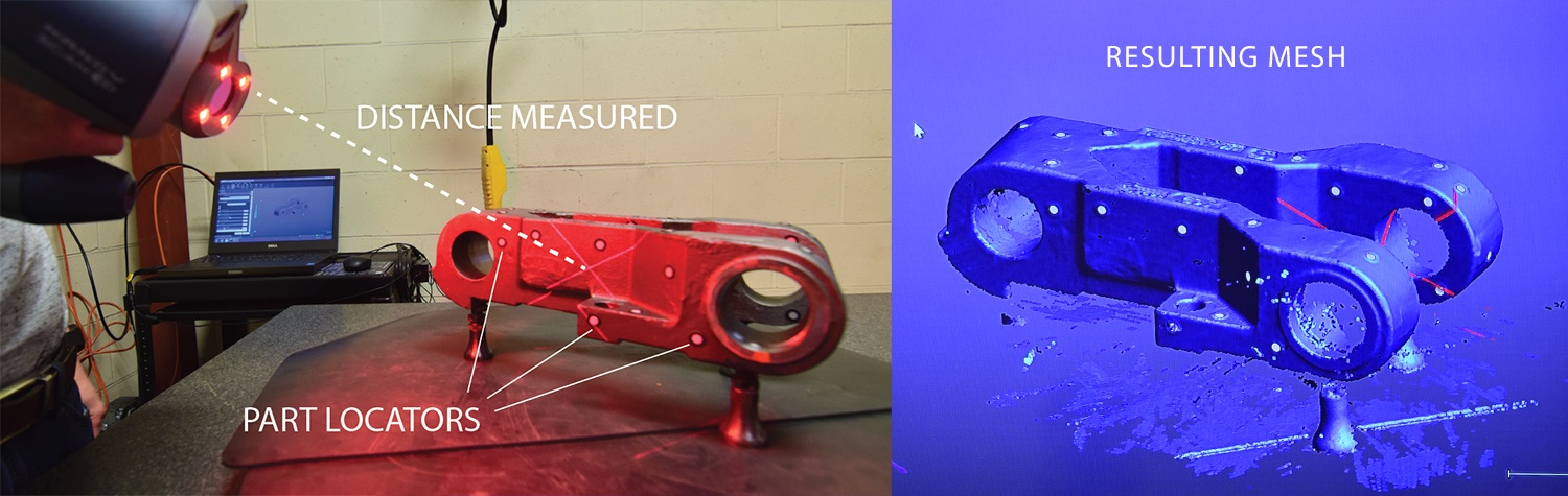
First, the operator orients the cast part in a way that exposes the surfaces to be measured. Then, they stick part locators on non-critical areas of the part. These reflective, circular stickers create a frame of reference for the scanner and separate the part from the background. As the operator moves around the part, or the part spins, the target points change in orientation and tell the scanning software how the scanner is oriented compared to the part.
The operator then activates a laser beam. As they move the crosshairs over the part's surface, sensor cameras mounted in the scanner measure the changing length of the laser beam. The scanner sends thousands, or even millions, of measurements to a connected computer, which interprets the measurements as a list of coordinates in three dimensions (X, Y, Z). Software can then convert those coordinates into a 3D visualization of the part.
Producing more accurate dimensional reports
For Eagle Alloy, laser scanning is a major asset for generating dimensional reports. As part of their APQP report, submitted along with sample castings for new products, they submit comprehensive dimensional reports. In addition to a 2D print with bubbled dimensions, Eagle Alloy is able to go one step further to offer a comprehensive, color-coded overlay showing exactly where the part is within tolerance and where it isn't.
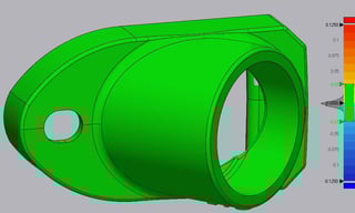 To create the overlay, operators first scan a sample part using the process outlined above. They then import a file with data from the scan into 3D modeling software that visualizes the scanned data as a mesh, or a 3-dimensional simulation of the part based on thousands of individual measurements. That mesh, representing a very close approximation of the actual part's dimensions, can be overlaid onto a 3D model of the part representing its nominal dimensions (the middle of the tolerance range). Operators then tweak the settings based on the tolerance range, and set colors to represent deviations from the center.
As an addition to the foundry's APQP report, this visual representation of tolerance fitting provides instantaneous feedback to the customer. Instead of analyzing 2D prints, bubbled dimensions or spreadsheets, the customer can take one look at the overlays and see whether or not the sample parts meet their requirements. Eagle Alloy can also provide customers with a 3D PDF file, allowing them to spin the model in virtual space, zoom in on particular characteristics, and obtain a complete picture of the part's tolerance conformity.
Laser scanning vs. traditional tools
Without laser scanners, foundries often have to use hand tools–like calipers, micrometers and height gages–to measure critical dimensions. While skilled operators can get very accurate measurements with hand tools, they present three disadvantages:
1) Hand tools don't measure curvature accurately: in order to measure degrees of curvature, or tolerances along a curved surface, operators using hand tools need to take a large number of readings. Even after measuring dozens of points, the curvature of a surface can only be estimated. The same is true of laser scanning, but with tens of thousands of points measured simultaneously, the resulting mesh is much more accurate.
2) Surface roughness creates challenges: even the smoothest cast parts have a degree of surface roughness. For parts with extremely tight tolerances, as-cast surface finish can provide sufficient variability to push the measurements out of the tolerance range. Laser scanning automatically takes into account surface finish, inclusions, and any other un-modeled characteristics to form a holistic view of the part's surface.
3) Some surfaces are inaccessible to hand tools: even with specialty hand tools, some intricate parts involve surfaces and characteristics that are difficult, or even impossible, to reach for accurate measurement. Laser scanners are limited only by the part's visible characteristics.
Other uses for laser scanners
Foundries that use laser scanners for inspection can also streamline the product development process for existing parts. In modern metal casting, every part begins with a 3D CAD file. That file can be drawn from scratch by a skilled engineer, given dimensional measurements from hand tools or a simple list of critical dimensions; or, the file can be adapted from a 3D scan of the original product. The same mesh that can be overlaid onto the nominal dimension model to inspect a part can be converted into a 3D model, which can then be optimized by foundry engineers.
For more on reverse engineering with laser scanners, stay tuned to the Eagle Group Blog for a reverse engineering case study.
Curious about working with the Eagle Group? Find out what we can do with our Tolerances, Capabilities and Design Recommendations reference guide:

Tags: Metrology, Product Design, Development, Inspection, Product Development, Technology, 3D Scanning

Written by Jeff Cook
Jeff Cook is Chief Sales and Marketing Officer for Eagle Alloy in Muskegon, MI. While enlisted in the Marine Corps Reserves, he began working at Eagle Alloy in 1986 as a snag grinder on 3rd shift after his father told him to “Get a job!” Jeff is past President of the American Foundry Society. His passions include educating young people on the careers and advancement available in the metalcasting industry.